. . . . . . . . . . . . . . .
. . . . . . . . . . . . . . .
Motivation
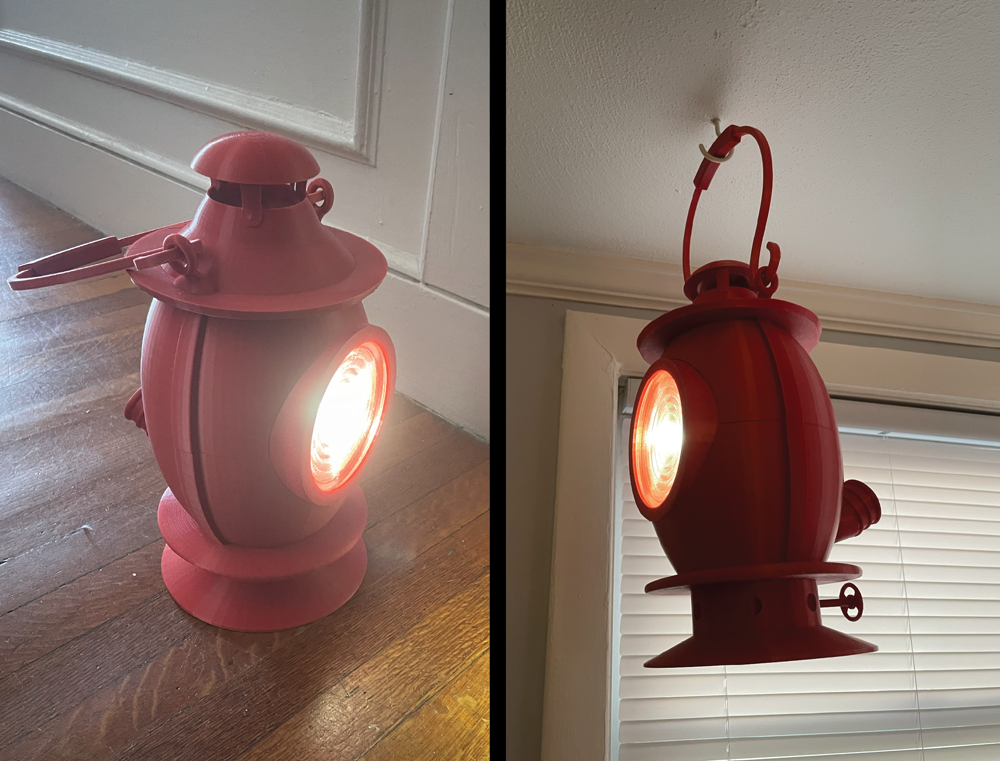
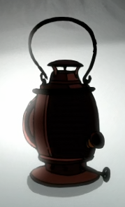
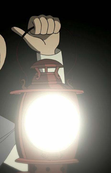
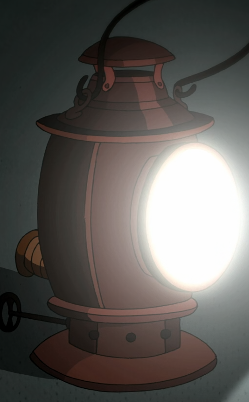
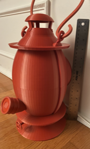
11 years ago Cartoon Network released one of the best miniseries ever made, Over the Garden Wall. It follows two boys lost in the woods, searching for the way home through The Unknown. Featured heavily in the story is the so-called Dark Lantern. As a fan of the show I wanted to build a physical version of the lantern, of a size proportional to that in the show. Many other 3d-printed models of the lantern with lights in the center, end up having the light bleed through the printed material, which I find ruins the illusion so to speak. Unless printing with full infill, and even then depending on the strength of the light, light bleed will result unless there is a reflector and lens contained within the model. Therefore, I designed mine with those components in mind. The lantern is about 31 cm tall, not including the handle, and weighs 1.29 kg. I'll go through the assembly instructions on this page, and if anyone would like to build their own, the .STL files are available on my GitHub. Instructions can be found there as well, though slightly less interactive. Speaking of which, please hover over the bolded and underlined part names to see previews of parts.
Materials
...and of course, your choice of filament. I used this, the Deep Red PLA from Ender Creality, as I found the color to match quite well to show's.
Assembly
The lantern is divided into 3 main sections that can be constructed independently, then combined. The Top only consisted of printed parts, apart from the three screws/nuts that hold the larger pieces together. The Front is essentially the necessary components to hold and position the main lens. The Bottom holds all the electronics, the batteries, LED, LED driver, and switch. A soldering iron is needed, as well as extra wires for the connections. The bottom and top sections slide together and the front slides into both, rotating into a locking position that secures all three.
Top
6 printed pieces, 3 screws/nuts
- Hood
- Main-Top-Half
- Cap
- Handle-Grip
- Handle-Halves (2)
Procedure
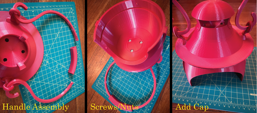
Put each Handle-Half through the rings on the Hood. Push the split ends through the Handle-Grip to lock them in place. Make sure to push as far as possible. It is possible to take them out again if absolutely necessary, but quite difficult. To connect the Main-Top-Half to the Hood, three screws will be placed through the top of the Hood, and match to nuts on the inside of the Main-Top-Half. The order of these steps is non-essential, but make sure to have screws and nuts in place before gluing the Cap to the top of the Hood.
Front
2 printed pieces, Main Lens, Tin Foil, Tape
- Front-Ring
- Front-Ring-Inner
Procedure
The main lens fits into Front-Ring, with Front-Ring-Inner sliding in behind, which is able to rotate after a certain distance, locking both in place. A few strips of tin foil can then be placed along the inside of the Front-Ring, secured with tape, for the purpose of preventing any light bleeding through the side of the ring. Some light will inevitably bleed through the very front of the Front-Ring, but it is difficult to notice due to the brightness of the light itself through the glass.
Bottom
The Bottom section of the lantern is the most complex and contains the necessary wiring and LED components. It is best assembled in the following stages:
Spout
4 printed pieces, Switch salvaged from flashlight
- Spout-Button
- Spout-Base
- Spout-End
- Spout-Wire-Punch
Procedure
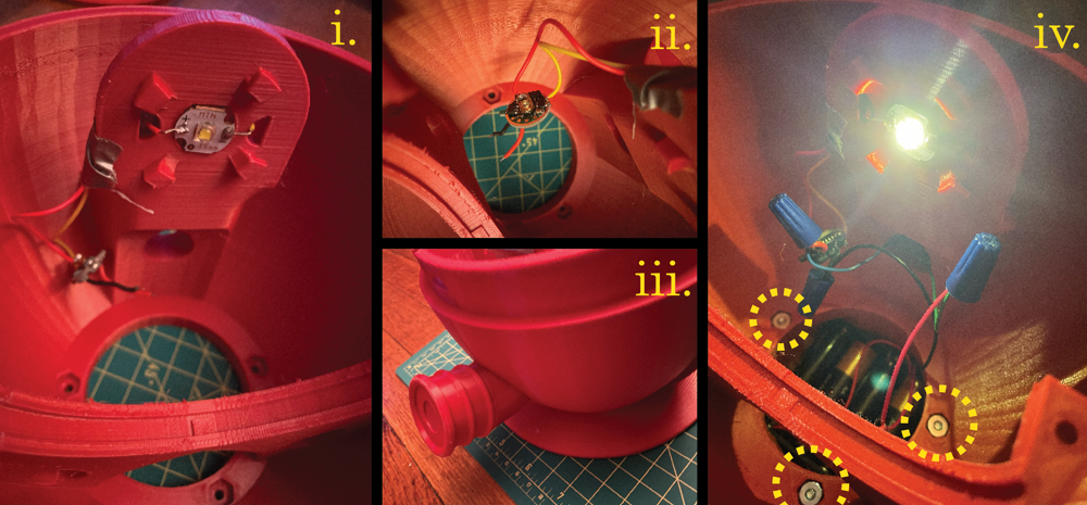
The spout holds the ON/OFF button switch, the actual switch component salvaged from a flashlight. As seen in (i.), Switch-Wire-Pinch, allows for a wire to be looped through the small hole and along the outside, pinching it to the inner section of the switch. Another wire will then have to be soldered to the middle section of the switch. (ii.) The Spout-End holds the Spout-Button, while (iii.) the switch sits within the Spout-Base. Both wires from the switch will eventually be snaked through the hollow part of the Main-Bottom-Half. (iv.) The Spout-End and Spout-Base slide and rotate to fit together.
Battery
Battery holder, additional wires
Procedure
The battery holder is designed to hold 4 AA batteries in series, which would provide approximately 6V. However, the LED Driver is expecting an input voltage of 2.8V to 4.5V. But, with a couple of cut connections, and a couple more added, I modified the part to place the two halves in series, connected together in parallel, to give the required ~3V. The green dotted lines represent the built-in connections on the battery holder. The purple X's represent the connections you'll need to sever. The blue dotted lines are the connections you'll need to solder with extra wires. The soldering will need to be done quickly and carefully, as heating the metal attachments with the soldering iron for too long will melt the plastic of the battery holder. And obviously, do not do the soldering with the batteries in place.
Base, Axle, Wheel
3 printed pieces, Altered battery holder
- Axle
- Wheel
- Base
Procedure
The (i.) The axle fits into the wheel, and (ii.) the hole in the base. Both should be secured with glue. (iii.) Lastly, the battery holder will fit into the base. The hole in the base has a divot (white dashed circle) that gives extra space for the battery leads. Note: The photo was taken before altering the battery holder, but it should be altered before adding.
Electrical Circuit
LED, LED Driver, Completed base and battery holder, completed spout, 3 screws/nuts, additional wires
- Main-Bottom-Half
Procedure
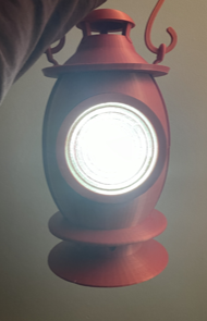
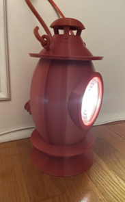
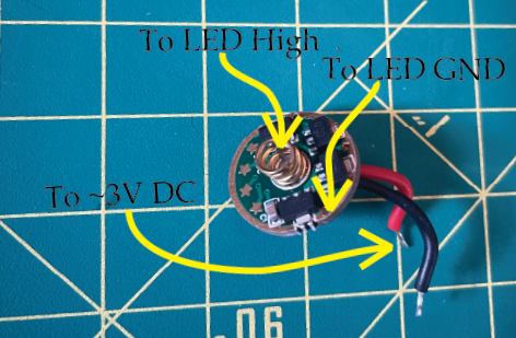
(i.) The LED should be glued to the indent at the top of Main-Bottom-Half. Wires to the LED pads should be soldered before gluing. Once glued, the wires can be maneuvered through the nearby holes where they will eventually be attached to the LED Driver. (ii.) Attach the wires you've soldered to the LED to the LED Driver, as directed by the graphic above. The spring on the LED Driver is high, and the coated edge is the ground. Solder the wires, using any of the holes along the edge for the ground connection. (iii.) If you haven't already, connect the spout to the Main-Bottom-Half. Pull the wires from the switch through the hole in Main-Bottom-Half. (iv.) Finally, connect the completed Base and battery to the Main-Bottom-Half with 3 of the screws and nuts. The electrical circuit is extremely simple: One end of the battery module is connected directly to the LED Driver, while the other is connected with the switch in series. By this point, the outputs of the LED Driver should already be connected to the LED. Though in the photo I connect the wires with twist connections, this was only for testing. For the final version I recommend soldering. Note: The power, driver, and LED are rather substantial, so the lantern is able to produce a fair amount of light. However, the reflector and lenses were chosen only for their size and appearance, not their optical properties and as such the “throw/flood” and light distribution were not taken into consideration or designed around. In any case, the light produced is quite bright and at a wide angle, which seems fitting given the appearance of the lantern.
Inner Additions
Completed Electrical Portion, Reflector, Inner Lens, 2 screws/nuts
- Inner-Ring-Top
Procedure
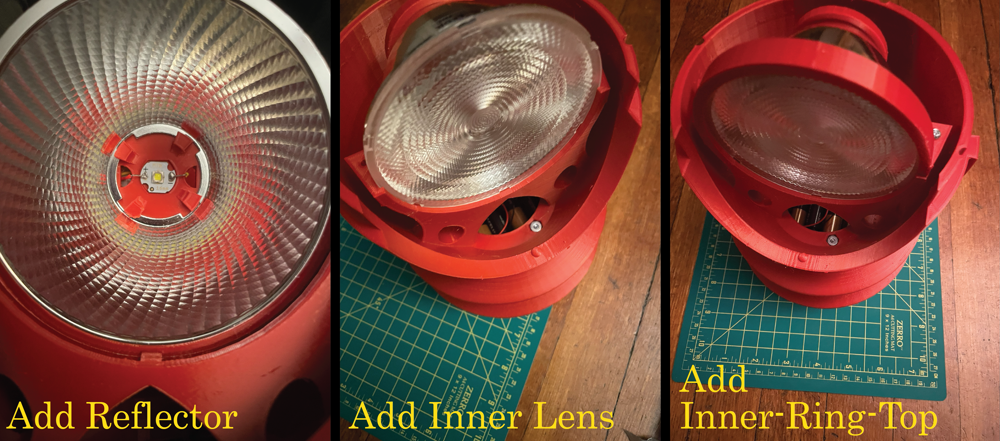
Add Reflector. The 4 pegs surrounding the LED are designed to allow for the Reflector to slide into and rotate to hold. The wide part of the Reflector will sit within the cylindrical trough. (In the photo in may appear that the lip of the Reflector is behind the piece, but it is the red being reflected which is causing it to appear as such.) Add Inner Lens. The peg within the trough will fit into the divots on the edge of the lens, ensuring it will not rotate. Add Inner-Ring-Top with two final two screws and nuts.
Final Assembly
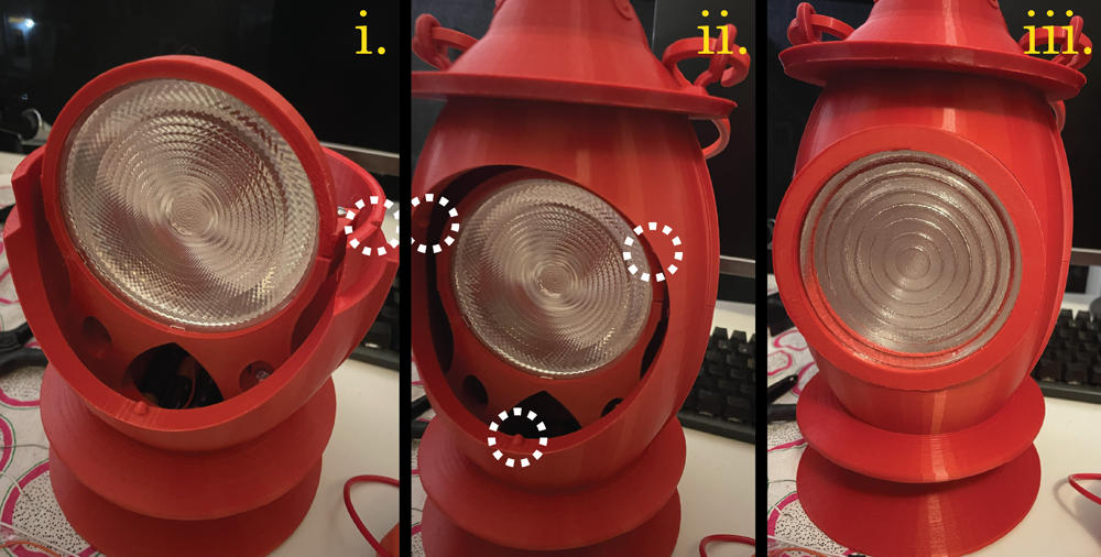
(i.) The Top and Bottom sections fit together via 3 grooves on the Bottom section (only one is visible in the photo), and 3 corresponding bumps on the inside on the Top section. (ii.) A similar method secures the Front to the other two sections. The 3 bumps are seen in the photo above. Be aware that the Front only fits with a single orientation, as the longest of the grooves needs to be placed at the bottom bump. (iii.) At this point the Lantern should be completely assembled, and able to turn on with the button at the back!